
8 May 26
Split Keyboard Build (Part 3) - Redesign
Complete Legless Redesign
After an age of deliberation on my previous keyboard design, I finally discarded it because I couldn't get an adjustable leg design that would allow the keyboard to be low enough on the desk.
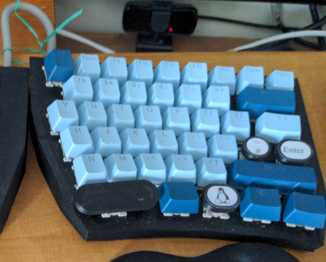
I decided to try and copy the surface curvature of my previous Microsoft Sculpt keyboard but with two separate panels.
Then I decided I would have a centre panel with a numpad and cursor keys.
I also decided I would 3D print my own keycaps because I couldn't find any that I liked with a UK layout.
I regret several of the decisions I have made, but I do have a working USB keyboard.
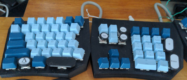
I had to abandon my 3D printed keycaps because I had not made the shaft long enough and a bunch of them didn't press far enough to trigger the switches.
I had previously bought a super-cheap set off ebay, so I used them to replace a bunch of my derpy printed ones.
The Coding
The ArduinoIDE library for USB HID keyboards is intensely annoying. It expects you to pass it ASCII characters instead of key codes, but it doesn't have a UK layout.
So I ended up gutting it to use the USB keycodes for everything except the modifier keys. This meant I had to literally overwite the library source in the arduino directories and make sure I never update the code for the RP2040/2350 boards or I'll lose my changes.
I also had to add a debounce timer for each key. To avoid adding too much latency, instead of storing the previous key state as 0 (pressed) or 1 (unpressed) I stored -DEBOUNCE_TIME or DEBOUNCE_TIME.
If the previous state was less than 0, I incremented it. If the previous state was larger than 1, I decremented it. Only if the previous state was 0 did I actually check it against the new state of the key.
Once I had fixed the switch bounce, I discovered a really weird artefact which led me to properly understand why diodes are important when wiring switches into a matrix.
Why the Diodes are Important
The problem my keyboard exhibits is this: hold S, hold E, press D --> get S and E as expected, then a W press followed by a D press....I mean...W?!!!
I started looking up RP2350 GPIO/pull-up timings and all sorts...
...until I found a post by Ben Chapman describing a lovely technique for soldering wires that I will definitely use next time.
...but why diodes?
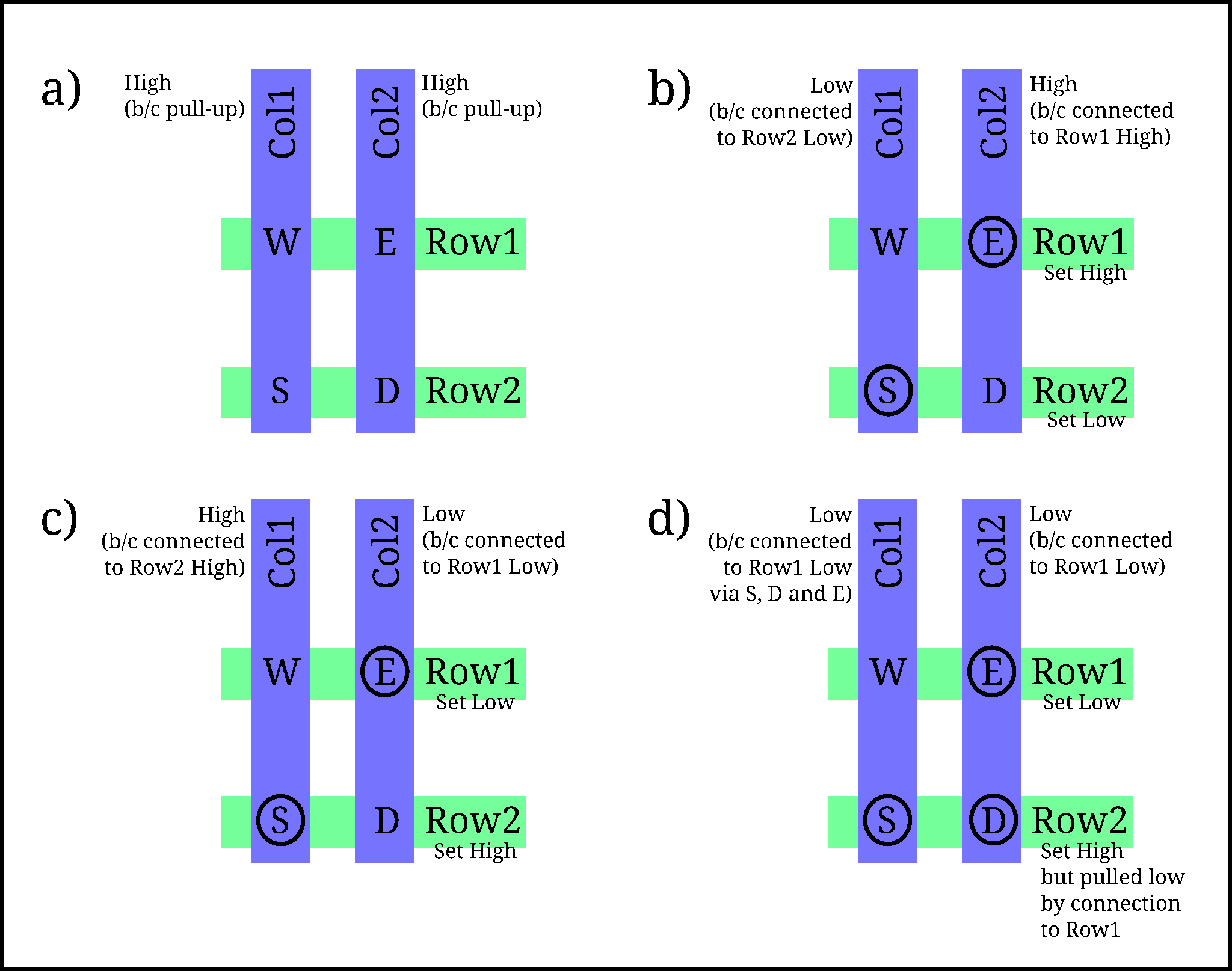
Diagram a) shows the matrix wiring for the W, E, S and D keys. In this case, the rows will be set high/low by the microcontroller and columns are connected to input pins, each with a pull-up resistor.
Diagram b) shows the microcontroller reading Row2 by setting it low and detecting which columns are pulled low by current flowing through the switch connections to Row2.
Diagram c) shows the microcontroller reading Row1 by setting it low and detecting which columns are pulled low by current flowing through the switch connections to Row1.
These are all as it should be. However, diagram d) shows what goes wrong when the D key is also pressed.
In diagram d) the microcontroller is trying to read Row1 by setting it low. As previously, Col2 is pulled low because of the E key being pressed.
However, this time the D key is pressed as well. This will allow current to flow out of Row2, through Col2 and into Row1 (because there is no diode to stop it).
Once Row2 is pulled low, current can flow from Col1 through the S switch to Row2, then via the D and E switches to Row1.
With Col1 pulled low, the microcontroller thinks that the W key has been pressed.
So this is why every switch in a matrix setup needs a diode to stop current from a 'high' row flowing through to a 'low' column.
(If you wire your keyboard the other way round with the columns set by the microcontroller and the rows as the inputs, the diode would have to be wired the other way round to stop current flowing out from a 'high' column to a low row.)