
17 April 2025
Split Keyboard Build (Part 2)
I modelled a keyboard switch mount and with some Blender scripting, I cloned it onto the key locations.
I then realised a mistake I had made: the key locations represented the top of the keycap, so I had made the panel and cloned the mounts in the wrong location!
With some edits to the code to allow for a z-offset from the key locations (in each local z axis), I could correct that and produce a second panel mesh for the bottom side of the panel.
It's been really useful to be able to tweak the key location script and regenerate the entire panel and all the switch mounts with a single button click. That allowed me to tweak the positions and re-generate the panel to see what effect it would have.
Once I was happy, I did some manual modelling to make the upper shell for the left section of the keyboard.
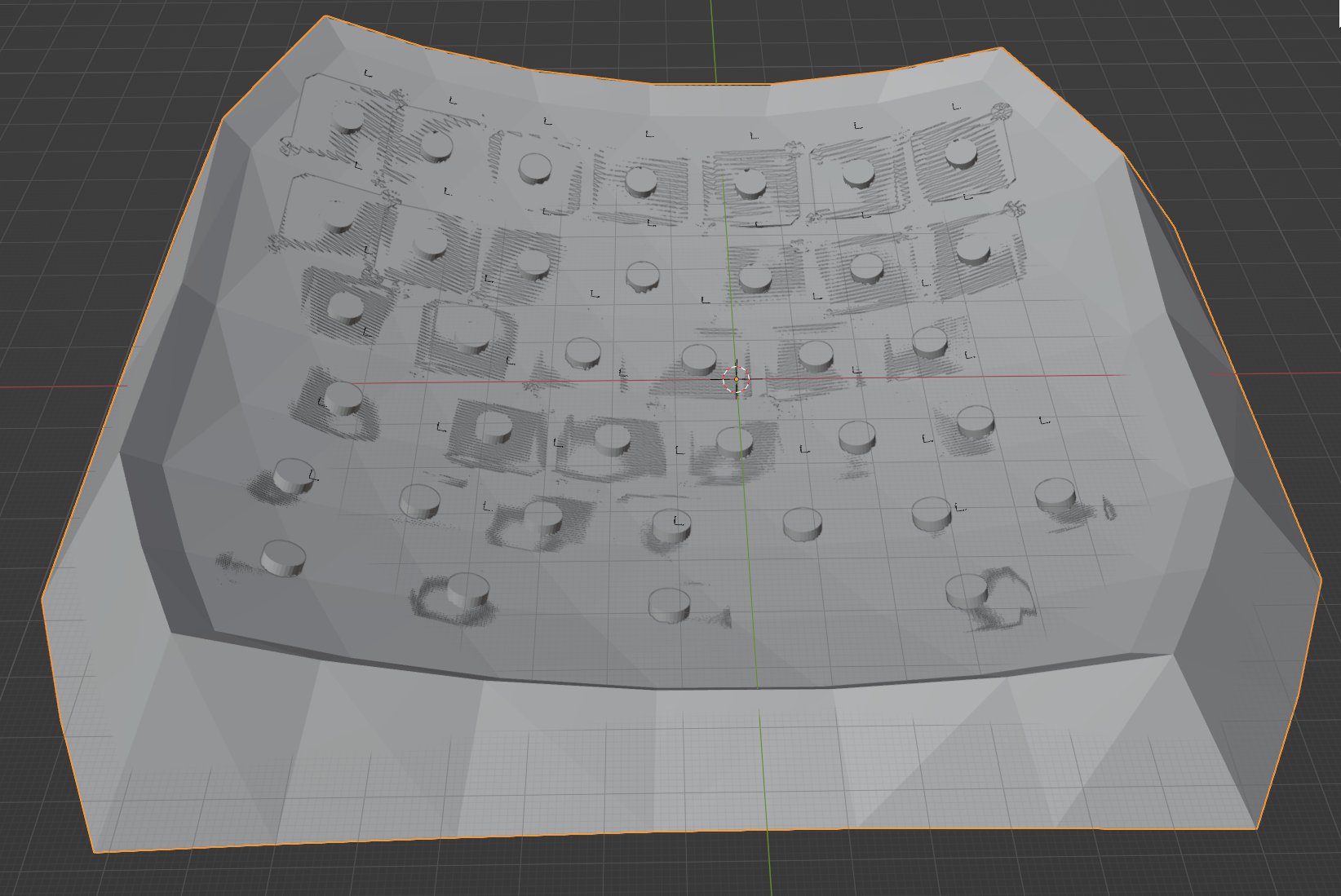
Each key cap is going to be made from 4mm radius aluminium rod, topped with washers (bonded with epoxy). Currently there are no holes for the rods to go through the upper shell. I need to clone a 4.5mm radius cylinder onto each key location so I can do a Boolean operation to subtract them from the panel. Then I should be able to print it and see what goes wrong.
Here is a picture of the underside:
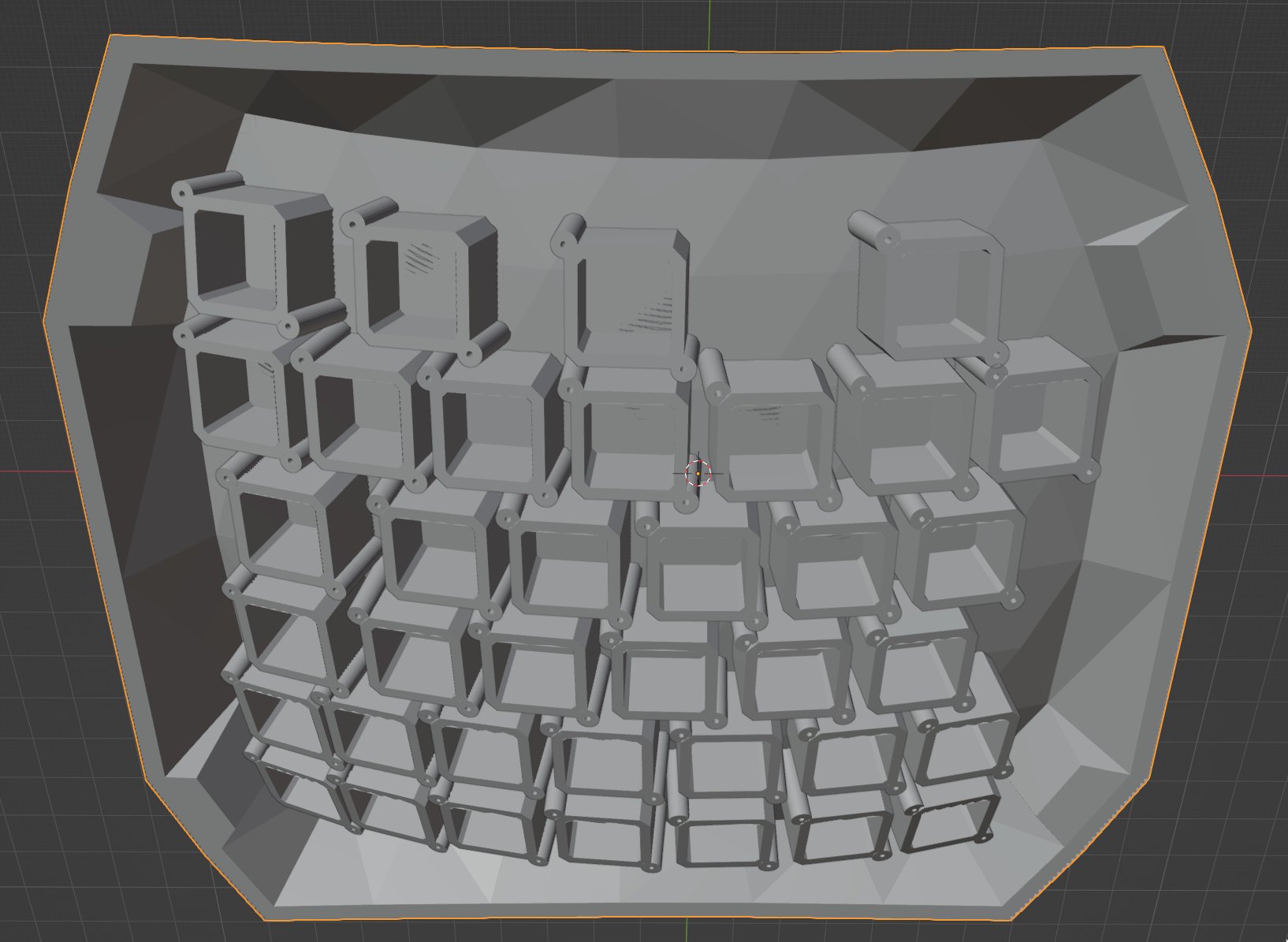
I made the panel 4mm thick, but I'm still a little worried the panel will be too flimsy to support the key mounts without some cross-beams. I didn't fancy trying to programmatically generate that geometry though, so I'm going to test print and test it out.